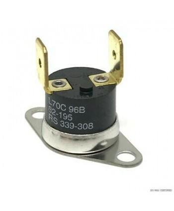
Explanation of the thermal switch
The thermal switch only needs to be connected to a simple and reliable circuit, and it can be easily used in a variety of applications. The following figure shows two interface circuits that contain thermal switches. In Figure 1(a), a double-contact mercury thermal switch is used on the assembly line as a cheap temperature detection device for small component furnaces. Insert this kind of temperature measuring instrument into the furnace, as long as the temperature is within the required range, the bulb will light up.

In Figure 1(b), two thermal switches monitor the wall temperature of the chemical container, which must be maintained between 45°C and 60°C when feeding. If the temperature is within this range, the relay is closed to allow feeding into the container, and if the temperature exceeds the limit, the relay is released and the feeding process is stopped. A resistance of 1.5 kilohms protects the contacts of the relay from overcurrent. The kick disc relay has such indicators as the minimum (dry circuit) current and the maximum contact current.
Thermal switch check
(1) Use an ohmmeter to measure the limit value of the thermal switch that controls the automatic choke door and the thermal switch of the intake pipe preheater pipeline, as follows Shown in Figure 2. Thermal switch 1 plug of automatic choke door: red. Specified value: The resistance value is 0 when the temperature is lower than 30℃; the resistance value is ∞ when it is higher than about 40℃.
(2) The thermal switch 2 of the intake pipe preheater pipeline, the specified value: the resistance value is 0 when the temperature is lower than 50℃; the resistance value is ∞ when the temperature is higher than about 55℃.
