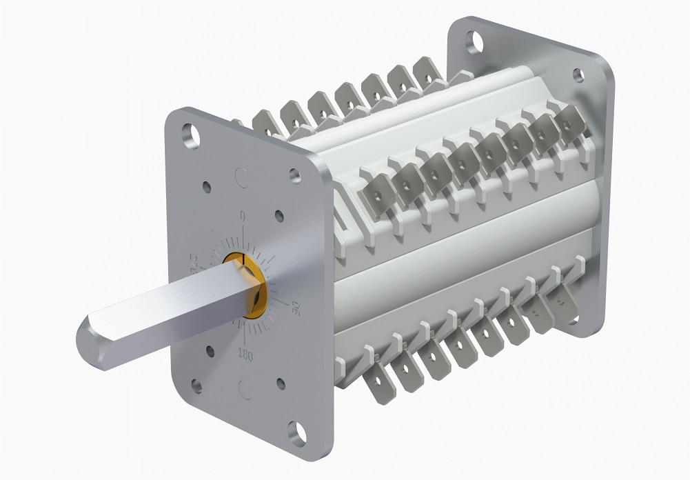
Switch definition
Auxiliary switch refers to a switch that contains one or several control (or) auxiliary contacts that are mechanically operated by a switch device. The circuit breaker relies on itself to drive the closing and breaking of auxiliary contacts (contacts) to change the opening and closing positions. To connect the circuit breaker mechanism closing and tripping control circuit and the audio signal circuit, to achieve the purpose of breaking or closing the circuit of the circuit breaker, and can correctly send out the audio signal, start the device and protect the locking circuit, etc. When the auxiliary contact of the circuit breaker is used in the same circuit for closing and tripping, there should be a delay.
Functional characteristics
Auxiliary switch is an accessory for operating mechanism for remote automatic opening and closing of circuit breakers. The electric operating mechanism has motor operating mechanism and electromagnet operation. There are two kinds of mechanisms. The motor operating mechanism is a molded case circuit breaker with a rated current of 400A and above. The electromagnet operating mechanism is suitable for a molded case circuit breaker with a rated current of 225A and below, (with a rated current of 400A) The contactor of the electromagnet operating mechanism and above, whether it is an electromagnet or a motor, their pull-in and rotation directions are the same. Only the position of the cam inside the electric operating mechanism can achieve closing and opening. The circuit breaker is in use When the electric mechanism is operated, it should be able to ensure the reliable closing of the circuit breaker under any voltage between 85% and 110% of the rated control voltage.
The auxiliary switch is suitable for molded case circuit breakers. The cover is equipped with a mechanism for rotating the operating handle. The shaft of the handle is installed in its mechanism matching hole. The other end of the shaft passes through the door hole of the drawer cabinet. The handle of the rotating handle is installed on the shaft head exposed on the door of the complete set. The round or square seat of the handle is fixed on the door with screws. This installation enables the operator to turn the handle clockwise or counterclockwise outside the door to ensure the closing or opening of the circuit breaker. At the same time, turning the handle can Ensure that the cabinet door cannot be opened when the circuit breaker is closed; the door of the switch panel can only be opened by turning the handle to open or buckle again. In an emergency, when the circuit breaker is "closed" and the door panel needs to be opened, press Rotate the red release button on the side of the handle base.
Operating environment
Affected natural environment factors
1. Altitude : Altitude has two main effects on high-voltage electrical appliances: (1) the impact on external insulation; (2) the impact on the heating temperature of electrical appliances
2. Ambient temperature; 3. Humidity; 4. Earthquake ; 5. Dirty; 6. Wind; 7. Ice coating
Conditions of use
1. Ambient air temperature: -40℃~+40℃;
2. The altitude of the installation site does not exceed 2000m;
3. The temperature and humidity conditions are as follows: the average relative humidity measured within 24H does not exceed 95%, measured within 24 hours The average value of the obtained water vapor pressure does not exceed 2.2Kpa, the average monthly relative humidity does not exceed 90%, and the average monthly water vapor pressure does not exceed 1.8Kpa, taking into account the condensation that occurs on the surface of the product due to temperature changes. p>
4. The acceleration is not more than 15m/square second;
5. The air is not significantly polluted by dust, smoke, corrosive and flammable gases, steam or salt spray.
Product classification
There are several types of auxiliary switches.
According to the number of opening and closing groups of the contacts, they are divided into: five open (50), four Open and close (41), three open and two closed (32), two open and three closed (23) There are six types: one open and four closed (14) and five closed (05);
According to the different terminal types, it is divided into two types: screw crimping type (Y) and plug-in type (C);
According to the structure of the push rod, it is divided into two types: buffer (H) and connector (L);
According to the specifications of the shell, it is divided into: high body (G) and Low main body (D) two kinds. And other forms of classification.
Technical parameters
Parameter name | DC contact | AC contact | < td width="66">|||
Rated insulation voltage | 660 | V | |||
Conventional heating current | 10 | A | |||
Putter stroke | 6.5/7.8 | mm | |||
Normally open contact spacing | 4.0±0.5 td> | mm | |||
Normally closed contact overtravel | 2.8±0.5 | mm | |||
Same-name contact synchronization | ≤0.3 | mm | |||
Rated voltage p> | DC110 | DC220 | AC220 | AC380 | V | p>
rated current | 6 | 3 | 10 | < td width="66">||
Maximum power-off current | 20 | 10 | 70 | A | |
Time constant t=20ms | Cosφ=0.4 td> | ||||
Life span | >40000 | times | |||
lmin power frequency withstand voltage | 2500 | V |
Common faults
If the auxiliary contacts are not Because of this, it should be reinstalled. If the drive rod of the auxiliary switch is broken or the roller falls off, the drive rod and roller should be replaced or the auxiliary switch should be replaced.

